|
|
|
RAPID PROTOTYPING AND TOOLING USING 3D SYSTEMS THERMOJET Permission is granted to make copies of this information for educational use only. Not to be used for any commercial purposes. Tim Lovett, September 2001: Nov 3 2001.
|
Update
Step |
Description |
Who Does it |
|
1 |
Team |
|
|
2 |
Team |
|
|
3 |
Feedback |
TL |
|
4 |
Modifications & re-send |
Team |
|
5 |
TL or CN |
|
|
6 |
Team |
|
|
7 |
(Team & CN) or TL for special cases. |
|
|
8 |
(Team & CN) or TL for very special cases. |
|
|
9 |
Part finishing and assembly |
Team |
Note: RP parts become expensive when they are large or require extensive finishing (eg gloss). The level of detail is relatively unimportant, so if you are designing something, feel free to add detail. (Although holes do add a bit of trouble, and parts that require more than 2 mould parts are more expensive to tool.)
Edge Radius (Internal & External Fillets)
Below 0.1mm. Remove them – they are wasting computer time and are too small for RP.
0.1 – 0.2mm. Barely visible in the RP model. You wouldn’t normally bother.
0.2 – 0.5mm. Consider this to be the minimal normal range for small radii.
Above 0.5mm: Fine
Note: Radii cause CAD files to grow significantly - especially when exporting to another file format such as IGES, STEP or STL.
Wall Thickness
Below 0.5mm. Can be done but probably requires special method (TL).
0.5 - 1mm. Consider this the minimum wall thickness for small features.
1 - 2mm. OK for most things, but could be fragile if over a large area.
2 - 3mm. Typical base thickness for larger area stability.
Above 4mm. Are you sure you need to go this thick for a part of this size?
Note: Parts made in 2 part resins have much lower shrinkage than standard thermoplastics used in injection moulding process. This means that sink marks will probably not show up, so keep track of likely sink mark areas and use your standard rules (eg 50% web to base thickness ratio or some other rule of thumb).
Exporting
For part inspection, I prefer Proe native files (Version 20), which is the version prior to 2000i. I need this to set the correct STL resolution also (althoug this can also be done in Proe). Most RP systems (as well as other techniques such as CNC) utilise STL files. These are a surface approximation of the solid part, built in triangles. (So an STL file does not actually represent a true solid object). The smaller the triangles, the better the approximation, but the files become larger. Typical STL resolution to suit the Thermojet would be 0.02mm and 15 degree plane angles. This is 1/2 the TJ resolution.
Other file transfer formats include IGES (well known but not too reliable) and STEP (seems to be more successful). Since I am using SOLIDEDGE, the preferred import format is PARASOLID, which is available from SOLIDWORKS and other programs that use the same solid modelling kernal (eg IRONCAD). There are actually only a few solid modeling kernals shared amongst the many CAD programs, which they license from the super-geeks that wrote them. Anyway...
Export: 1st Choice; Proe V20. 2nd Choice: Step. (Do not send STL- I will set these)
Sending
You must zip your files prior to sending. It is best to keep any emailed file to within 1 MB or so - definitely less than 3MB. (Although I have downloaded 8MB STL files - someone set the resolution too high!). Please use Winzip (I have PK zip floating around somewhere...?)
Email address. Please send direct to business email:
You should include your Team Number, the names of the team members involved.
To minimise costs, the Thermojet will only be run when a full plate-load of parts has been finalised. The first print will be on Thursday 15th Nov 2001, and parts will be available the next day, and will be distributed by Chris Nash.
Following prints will be scheduled on demand.
Feedback should be within 24hrs (wait 48 befre pannicking). I will be looking at some design issues like wall thickness, likely printing or casting problems, and whether it may require an alternative process for tooling. (Usually if too fragile to handle).
Support Columns
Overhanging features in a model need to be supported during printing. This produces a rough surface finish upon removal. For example, if you printed a solid ball, you would have the bottom hemisphere with rough finish and the upper hemisphere normal. These can be cleaned up with some care, but it can be difficult if there are fine features included in the surface. Breakage of the wax is always a danger during cleanup.
Choose the rough surface to be...
The underside or hidden side.
The less 'busy' side, so that it can be cleaned more easily.
The convex side, for ease of cleaning.
Improving the Surface Finish
The TJ wax can be smoothed using ordinary solvents such as enamel solvent and a lint-free cloth. This will remove the fine lines and steps produced by the resolution of the Thermojet. (A bit like anti-aliasing a CAD picture). Too much rubbing can drag the wax and cause poor finish. Too much solvent can make the wax 'craze' -fine surface cracks.
To smooth out the support column surfaces, a nylon stocking works well. Less aggressive solvents (eg White spirits - Dry cleaning fluid) are eaier to work with but require adequate time to dry out (overnight) before silicone.
After smoothing, the wax can be painted. Use 'oil' based paints. Enamel works well, although various automotive paints using standard thinners can be successful. Make sure you try it out first.
Occasionally, the part geometry allows cheating. EG a completely flat surface could be built thinner to allow a plastic sheet to be adhered. This will produce an excellent finish, but care should be taken to get a smooth edge.
Fixing Up Parts
Holes or blemishes can be repaired with a soldering iron to drip TJ wax onto the surface.
Modelers clay sticks to the TJ wax. Heat it up first to make it softer.
Major modifications are generally difficult in wax, but any model that holds its shape and is not porous will make a successful silicone tool. You can even combine pieces of RP with other forms of modelling such as plastics, metal and painted wood.
Parts can be glued with superglue (fragile joint but adequate for silicone tooling)
Parting Line and Holes
To mould a hole, the silicone tool must touch together to seal off the PU. This is known as 'shut-off' in toolmaking. If your part has a hole, you must cover the hole (neatly!) with tape so that the mould will pull apart. Use Magitape - some tapes interfere with silicone cure.
The parting line of the part might also be outlined using tape, to help produce a level parting line.
Moulding Boxes
Virtually any container will do the job (eg plastic lunchbox), or you can make your own in timber, plastic etc. Make sure you have enough space around the part to minimise distortion and adequately seal the PU during casting. Allow for expansion during de-gassing.
Typical allowances. Approx 50% larger than the part (linear dimensions), and at least 10mm around it.
Mounting the Part
The wax part must be suspended inside the moulding box with enough rigidity that it will not be dislodged during the pouring and de-gassing of the silicone. The feeder (gate) tube must be fixed to the part and this is usually the main support. Sometimes risers (vents) can be attached (these are usually much thinner) to help stabilise the part. The part can also be supported by attaching to the parting line tape.
Casting the Silicone
Wacker M4644 is a fairly viscous (thick) mixture, and it will expand about 4 to 5 times during de-gassing. You have approx 1/2 hour working time. It is non-toxic, (but not for implants).
It needs to be very thoroughly mixed due to its high viscosity differences and 1:10 ratio. De-gas the mixture in an oversized mixing container before pouring into the mould for a final de-gassing. When de-gassing the first time, the mixture should foam up and then collapse, indicating adequate de-aeration has been achieved. During the 2nd (moulding) de-gas, bring up to full vacuum and then hold for a few minutes, then leak for 1-2 minutes back to atm pressure. Small bubbles (<1mm) will dissolve after approx 10 mins. Try to keep it level.
Curing the Silicone
See Silicone data.
Standard Method
The Silicone tool is taped together (electrician's tape or rubber bands), and a feeder tube inserted.
You have only a few minutes to work with the PU. Mix PU, degass quickly and pour into large syringe. Inject into mould until vents leak. Block off feeder. Load into oven (See PU Data).
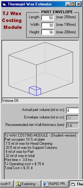
Running the program
|
|
SILICONE TOOLING TopCalculation of
silicone tooling costs is relatively straightforward.
Most silicone tools
would be 50% larger than the part, and usually form a simple rectangular
of circular shape (whose volume is easily calculated).
There is some loss
of silicone when it is left on container walls during expansion (5-10%).
Silicone Data:5.5kg
M4644 Silicone is $250 (inc gst).
($45.45
per kg, 4.545 cents per gram)
Density 1.07 gm/ml. (4.863 cents per ml). Hardness 41 Shore A Tensile Strength 5.5 Mpa Elongation 350% Linear shrinkage during cure 0.1% Coefficient of thermal expansion 2.5x10⁻⁴ mm/mmK Mixing ratio 100A:10B by weight Pot Life 60mins at 25 oC Curing schedule with TJ wax: 35oC for 5 hours Higher temp Curing schedule: 60oC/2hrs, 70oC/1hr Vacuum expansion after mixing: 4-5 times initial volume. Vacuum time: 5 minutes. Vacuum until expanding silicone foam collapses, then release vacuum slowly. Allow to stand while bubbles dissolve and silicone settles.
|
|
POLYURETHANE TopCalculation of PU
usage is even easier. Simply add volume of part + allowance for wastage,
overfilling etc. (approx 100% for small part down to 20% for large
parts).Typically add 50%. (Don’t cut it too fine in case you inject
air into the mould.
Polyurethane Data:TC880
Polyurethane costs $110 for 2kg. (inc gst)
($55
per kg, 5.5 cents per gram)
Density 1.12 gm/ml. (6.16 cents per ml). Hardness 80 Shore D Tensile Strength 38 Mpa Tensile Modulus 1.45 GPa Elongation 15.5% Linear shrinkage during cure 0.15% Mixing Ratio 100A:100B by weight (90A:100B by volume) Pot Life 4-5 minutes at 24oC Curing schedule: 50oC for 1 hr Optional post-cure schedule: 71oC for 6hrs (Supported or in mould for best mechanical properties) Gives HDT of 66 oC. Vacuum expansion after mixing: 4-5 times initial volume. Vacuum time: Very quick (10 seconds) once vacuum established. Release vacuum once bubbles have collapsed. |
CAUTIONAVOID REPEATED OR PROLONGED CONTACT WITH SKIN. IN CASE
OF EYE CONTACT FLUSH WITH WATER FOR 15 MINS AND SEEK MEDICAL ADVICE.
Use
in well ventilated area. Wear protective gloves and clothing. Approved
safety glasses must be worn at all times when handling this product. May
cause allergic reaction. Refer to MSDS before using this product. |
Rapid
Prototyping technology is being carried out in most major capitals in Australia,
except Sydney.
The
Queensland Manufacturing Institute (QMI) http://www.qmi.asn.au/
was one of the first RP + T facilities
in Australia, particularly in the areas of rapid tooling and value added RP.
QMI employ approx eleven people in this area, most of their commercial
business come from interstate - in particular NSW, Victoria and overseas. QMI is
Australian agent for 3D Systems, a US manufacturer of the SLA and Thermojet
systems.
The
South Australian Centre for Manufacturing which focussed on SLS
prototypes, was also set up as a technology transfer agency.
Private
companies have outperformed these quasi-government agencies with two major
players setting the pace. Current leader in RP business volume is Solid Concepts
(Perth ,WA), http://www.solid-concepts.com.au/
which has taken most of the market – particularly in the supply
of SLA prototypes. They have recently added a large model SLA machine and are
looking at FDM equipment capable of full size car bumpers. Used by car
companies, Resmed etc. Offer 5 day turnaround and competitive pricing -
Australia wide - on SLA parts. Approx 2 weeks on Silicone Tooling / Vacuum
Casting. Solid Concepts led the way in reducing RP prices, and recent quotes
indicate continuing price reductions, though limited by AUD$ and high cost of
SLA resin.
Another major private company is Silhouette (Melbourne) www.rapidweb.com.au which offers (through affiliates) a combination of SLA, FDM, SLS, LOM and the Actua 2000. They have expertise in RP tooling, vacuum casting, RP investment casting, low cost injection mould ‘bridge tooling’ and final production tooling. (Resmed)
Concentric Asia Pacific http://www.concentric.com.au/prototyping.htm now offers SLS technology (2000 & 2500 systems by US company DTM Corp), previously run by South Aust centre. Also run an LOM 2030, CAD services (Catia, Alias) and 3D scanning. (Digibot)
RMIT
has an SLA machine. Solid Concepts began a joint business to supply parts using
this equipment but the venture was unsuccessful. The director of Solid Concepts
sites poor quality and unsuitable work environment as factors in the failed
scheme, and has indicated his reluctance to join forces with a university.
Overseas,
Hong Kong is a major RP centre, 3D Systems is based there. Thermojet machines
are commonly used for silicone tool patterns. (Some 42 machines installed)
Sydney has no genuine RP bureau operating except UWS current RP machine. There is a Z402 (Z-Corporation) which has missed the wave as far as industrial prototypes are concerned – resolution is too low for most customers today. The UNSW has an Actua 2000 (predecessor of Thermojet), for internal engineering faculty use only, which is occasionally used by QMI when they get too busy. QMI has not had recent contact with UNSW machine. (Indicating that neither are too busy, and that QMI acquired a Thermojet).
Hycast
metals has recently acquired a Thermojet (mid 2001) used almost exclusively for
Investment Casting wax patterns. UWS has worked with Hycast on Olympic memorial
nameplates.
Sydney
has a few companies offering the equivalent of silicone tooling (Box & Dice,
Designamite etc), but not full vacuum casting equipment.