|
|
|
|
|
RAPID PROTOTYPING AND TOOLING USING 3D SYSTEMS THERMOJET Permission is granted to make copies of this information for educational use only. Not to be used for any commercial purposes. Tim Lovett, September 2001. |
Site Index
Update (WaxQuote instructions)
Comparison of RP Manufacturers
Contact Info: Ask Tim Lovett, Pricing your RP parts
Project Schedule & Tim Lovett availability
Casting Parts from the Silicone Tool
Industrial design often deals with parts which will be produced by a mould process such as injection moulding or die casting. These processes use an expensive tool and machine, but low material and labour costs during the production run. For most commercial quantities (say 10,000+), processes like injection moulding are the most cost effective. Unfortunately, tooling can be very expensive, a typical injection mould might be $10k for a simple part and $100k for a largish item, add more for special complexities such as sliding cores, high clarity, multiple cavities, complex detail etc. Add even more if you want to modify the design after you get the parts back. In the past, the designer would check & double check the drawings, post them off to the toolmaker, and then endure a nerve-racking several months wait for the first off tool samples.
It can be difficult to design something right first time. All the more so when the product is a complex combination of many parts. In some cases, bridge tooling is used which may never be used for production runs. These tools may be machined in aluminium or unhardened steel. E.g.. Parts for medical equipment which must undergo a lengthy testing and certification process in the exact production material. Alterations are almost inevitable. CAD has helped the designer to be more certain of the design. Parts can be checked for assembly functionality, analysed for stress and deflection, and evaluated in a simulated injection moulding process. While it is possible to go direct from CAD to production tooling, there is still plenty of call for a solid object for evaluation (form, fit & function), marketing, testing and just plain old 'gut feeling'.
Rapid Prototyping (RP) is another tool in product design. It refers to parts that are built direct from a CAD file using a layered approach. (Also called layered manufacturing). The main alternatives to RP are CNC and hand crafting. CNC offers advantages in higher precision and wider material choice, but is less suited to the modeling of injection moulded parts with their typical thin walls and awkward internal details. The use of hand crafting has diminished to such areas as early form models, larger models where RP costs are excessive, and non-critical geometries.
Silicone Tooling is a means of duplicating parts in castable polymers such as Polyurethane and Epoxy. A master pattern is made (usually by RP), then encapsulated in silicone rubber which is then cut open to form a mould. The master is removed and liquid resin is injected into the mould and cured. These parts are cheaper than RP models and a variety of materials can be used - ranging from soft rubbery silicones to high strength epoxy.
There are further developments which take the master pattern and produce a metal filled epoxy or sintered tool insert which can be used in the injection moulding process. The high pressures of injection moulding requires a very rigid tool design, so these parts are usually inserted into a hollow steel mould which locates and supports the insert. Another use of the silicone tool is for investment casting patterns - wax copies of the part which will be coated in 'plaster', melted out and then filled with molten metal.

Fig
1: Market share for top 10 RP Manufacturers:
Compiled from The RP Directory 1999
Few ‘in-house’ systems were listed. The customer base for lower end systems (‘desktop manufacturing’) is considerably higher than indicated in the report. However, financial figures secured for the public companies show a similar ranking to this figure
3D Systems (SLA & Thermojet)
26081
Avenue Hall, Valencia, CA 91355
Fax:
661-294-8406
Email:
moreinfo@3dsystems.com
Internet: http://www.3dsystems.com
Aust
Distrib. (QMI)
Brisbane
Technology Park
Eight
Mile Planes, Brisbane 4133
Stratasys, Inc. (FDM)
14950
Martin Drive, Eden Prairie, MN 55344-2020 USA
Ph:
+1-612-937-3000
Fax:
+1-612-937-0070
Email:
info@stratasys.com
Internet:
http://www.stratasys.com
Aust
Distrib. (Imag Australia)
711
High St
East
Kew, VIC. 3102
Contact:
Mr Mario Paglia
Tel:
+61 3 9810 2105
Fax:
+61 2 9810 2153
Z Corporation (3DP)
35
Medford St, Suite 213, Somerville, MA 02143,
Ph:
+1-617-628-2781
Fax:
+1-617-628-2879
Internet:
http://www.zcorp.com
Aust
Distrib. (Intercad Pty Ltd)
3/10
Rodborough St
Frenchs
Forest NSW 2086
Contact:
Mr. Julian Spencer
Tel:
02 9975 7133
Fax:
02 9975 7169
Helisys Inc. (LOM)
24015Garnier
St, Torrance, CA, 90505-5319, USA
Tel:
310-891-0600
Internet:
http://www.helisys.com/
Aust
Distrib (TOPTEC Australia Pty. Ltd.)
1/28
Lauretta Street
Newton, SA 5074 Australia
Contact: Mr. Dirk Seret
Tel: 61-8-8365-0650
Fax: 61-8-8365-0662
DTM
Corporation (SLS)
North
America:
1611
Headway Circle, Building 2, Austin, TX 78754,USA
Ph:
+1-512-339-2922
Fax:
+1-512-832-6753
Internet:
http://dtm-corp.com
Asia/Pacific:
7
Temasek Blvd., 44-25 Suntec Tower One, Singapore 038987
Ph: 65-430-6678
Fax:
65-430-6679
EOS
Gmbh Electro Optical Systems (Laser Sintering)
Pasinger
Str. 2
D-82152
Planegg / München, Germany
Tel.:
+49 (89) 856 850
Fax
: +49 (89) 859 84 02
Email:
info@eos-gmbh.de
Object Geometries (Objet)
US Tel: 908 228-5400
Israel: +972-8-940-9717
Internet
http://www.2objet.com/
Email: info@objet.co.il
Reference:
Financial
reports for US public companies. DTM Corp (DTMC), 3D Systems (TDSC), Stratasys (SSYS)
http://earnings.nasdaq-amex.com
Rapid
Prototyping Directory 1999, Cadcam Publishing,
Wohlers
Associates Inc. http://www.wohlersassociates.com
Estimates
4259 RP machines sold in 10 years 1988-1998. Refer Rapid
Prototyping & Tooling State of the Industry: 1999 Worldwide Progress Report.
NASA,
MSFC's RP lab. http://nasarp.msfc.nasa.gov/
Comparison
of major RP systems – hourly running costs. (Refer append 2)
Rapid
Prototyping Electronic Mailng List RPML,
Forum
for RP discussion – good for finding out little problems with machines.
Images are from respective manufacturer's websites.
SLA 3500http://www.3dsystems.com/
Mid range SLA machine. Builds parts in UV sensitive epoxy using the SLA technique. The 3D Systems SLA machines are the most popular choice for typical RP work-especially service bureaus. SLA machine range includes SLA 250, 3500, 5000, 7000.
+ Good resolution & surface finish + Fairly strong parts + Fairly easy to finish parts - Requires support removal - High material cost - Little choice in materials
|
A UV laser traces out successive contours of the a part on the surface of UV sensitive epoxy. With each layer the platten lowers into the liquid resin. Supports are built to hold the part to the platten. The part is cured to ensure full hardening. Supports are broken off and the part is usually smoothed by mechanical sanding or blasting.
|
 |
|
FDM 3000
Mid range FDM machine. Builds parts in ABS using the FDM method. Mechanical properties of parts direct from the machine approximate injection moulded parts. Also has flexible ABS material and choice of several colours.
+ Thermoplastic properties + Low material cost + Dissolving supports - Slow - Striated surface finish
|
Like toothpaste from a tube, the FDM technique extrudes a thin 'road' of thermoplastic through a heated die under CNC control. The part build up in successive contours with supports made from a dissolvable material. |
 |
|
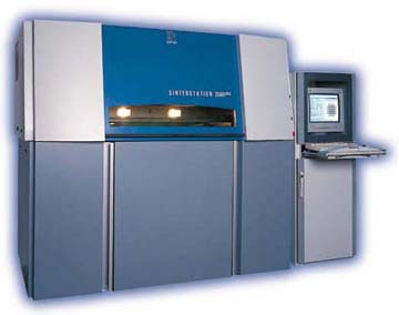
Sinterstation 2500
DTM corporation's Sinterstation 2500 machine. Builds parts in variety of materials using the SLS method. Materials include Nylon, glass filled Nylon and other filled polymers. Mechanical properties are good for functional models, but doesn't match SLA resolution.
+ Low material cost + Variety of materials - Poor surface finish - Difficult to work |
A laser fuses powder together in successive layers forming contours of the part. The powder has a supporting effect, and is removed to reveal the part.
|
 |
|
LOM 1015H
The Helisys LOM machines have their place in the less intricate products and larger parts (although this also suits CNC). The finished parts resemble wood. Large model size offered by 2030H machine.
+ Low material cost + Easy to work - Difficult for intricate parts - Anisotropic material properties
|
A laser traces out successive sheets of paper which are laminated together to form a block. Each sheet is square but contains the part contour with cross-hatched excess support material. The excess blocks are removed to reveal the part. |
 |
|
Sanders Patternmaster http://www.sanders-prototype.com/
The Sanders Patternmaster builds parts in a wax material with a high resolution. Suitable for building patterns for investment casting and vacuum casting. Used in jewelry industry.
+ Good resolution + Dissolving supports - Slow - Wax only
|
Sanders Technology
The Sanders machine is one of several RP machines utilising jet technology similar to inkjet printing. The Sanders machine jets heated wax in successive layers, using a dissolvable support material for overhanging features. The jet has only a few apertures, making it rather slow. |
 |
|
Z-402
The Z-Corp machine builds models quickly and requires no support structures. Material is cheap but lacks resolution.
+ High speed + Cheap material - Poor surface finish - Infiltration process |
Z Technology
The Z-402 is another inkjet style machine. Layers of powder are printed with binder by an ink-jet mechanism, followed by strengthening by applying adhesive or wax. Very similar to SLS but without a laser. |
 |
|
3D Systems' jet technology machine. Parts are strong enough only for concept models (form) but are suitable for investment and vacuum casting patterns. Resolution is good on upper surfaces.
+ Good resolution + Clean operation - Supports - Wax only |
TJ Technology
The Thermojet (TJ) is similar to the Sanders machine except that it prints through larger number of holes. No support material is used, so parts are held on columns of wax which are broken off afterwards.
|
 |
|
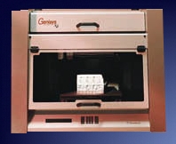
Genisys
Desktop modeller from Stratasys. Builds parts in rougher version of FDM method, which are relatively robust compared to Thermojet, but lower resolution.
+ Quick for Thermoplastics - Poor resolution & surface finish
|
Genesis Technology
Same as FDM but not as fine. The diameter of the extruded road is much larger and quite obvious. |
 |
|
Objet Quadra NEW
Beta
release late 2000, commercial release 2001. High resolution inkjet style
printing with photopolymer materials. + High resolution 600x600x1200 DPI + Mid size 270x300x200mm + High speed + Dissolvable supports - (Material cost might be a negative factor here - unknown at this stage) |
Objet Technology
A new jet technology combining inkjet speed & resolution with strength of photopolymer. Rather like a cross between Thermojet & SLA. Also prints a dissolvable support material like the Sanders & FDM machines. |
 |
SLA
- Stereo-Lithography
Apparatus - 3D Systems
Top
|
Advantages Good
resolution Widely
used Epoxy models fairly strong |
Disadvantages Expensive
machine. Expensive
material Laser
life and maintenance Moisture/temp
sensitivity Some
brittleness of model Requires support structures |
|
|
Applications Injection
mould prototypes, Patterns
for vacuum casting Patterns
for investment casting (direct) - 'Quickcast' Patterns
for 'Keltool' high volume injection tool inserts Form, fit and (some) functional testing |
||
|
How
it works. A
UV laser
which cures the resin is reflected to trace out successive contours of
the object. The bath of resin (a photo-sensitive polymer-epoxy) contains
a lowering platform, and each successive layer is traced on the liquid
surface. The next layer of resin is swept over the part to ensure
consistent thickness. When complete, the part is removed and post cured to ensure complete hardening. |
|
FDM
- Fused
Deposition Modeling - Stratasys Top
|
Advantages Material
properties near ABS Cheap
material Flexible material option |
Disadvantages Slow
process Expensive
maintenance Requires support structures but removable |
|
|
Applications Injection
mould prototypes, Patterns
for vacuum casting Form, fit and fairly good functional testing |
||
|
How
it works. Heated
ABS is extruded through a fine nozzle under control of 3-axis CNC. This
'road' is built up in layers, the plastic solidifying as it cools. The
resulting part has layered grain structure but achieves up to 70%
strength of moulded ABS in XY plane. The
fine nozzle is responsible for the slow build times (can be more than 24
hrs). Flexible ABS material is available but requires additional
extrusion head. Best
suited to thin-walled structures (Injection mould parts). |
|
SLS - Selective Laser Sintering - DTM Corp Top
|
Advantages Variety
of materials Reinforced
plastics (Glass/Nylon) Good
part stability (Heat/chem) No supports required |
Disadvantages Poor
surface finish Reduced
resolution Laser life and maintenance |
|
|
Applications Injection
mould prototypes, Form,
fit and functional testing Reinforced (glass fibre) and filled composite materials |
||
|
How
it works. A
laser
which fuses the powder is reflected to trace out successive contours of
the object. The powder (plastic or plastic composite) is held on a
lowering platform, and each successive layer is traced on the top
surface. The next layer of powder is swept over the part to ensure
consistent thickness. When complete, the part is removed. |
|
LOM
- Laminated Object Modelling - Helisys
Top
|
Advantages Cheap
materials; paper/ plastic Good
part stability (Heat/chem No
support structures Larger model sizes available |
Disadvantages Anisotrpic
(Weak vertical webs) Laser
life and maintenance De-cube and post-work |
|
|
Applications Form,
fit and (few) functional testing Patterns
for casting Good for thick walled parts |
||
|
How
it works. A
laser
traces out successive layers in heat-adhesive paper, which is bonded to
the built-up section below. The platform is lowered and the sheets
bonded until the part is built. When
complete, the diced sections are removed both inside and out. After this the part is usually lacquered to exclude moisture. |
 |
Members of the lab have taken the time to perform a cost analysis of RP production. After consulting the makers of our processes and considering several factors (i.e. cost of materials, wear-and-tear of machines, etc), MSFC's RP lab has adjusted production prices accordingly. Below you will find helpful tips to selecting the right process for your part along with an approximate cost to produce it.
|
Machine |
Cost |
Response Time |
Material |
Application |
|
Fused
Deposition Modeler 1600 (FDM) |
$10/hr |
2
weeks |
ABS
or Casting Wax |
Strong
Parts Casting
Patterns |
|
Laminated
Object Manufacturing (LOM) |
$18/hr |
1
week |
Paper
(wood-like) |
Larger
Parts Concept
Models |
|
Sanders
Model Maker 2 (Jet) |
$3.30/hr |
5
weeks |
Wax |
Casting
Pattern |
|
Selective
Laser Sintering 2000 (SLS) |
$44/hr |
1
week |
Polycarbonate
TrueForm SandForm |
Casting
Patterns Concept
Models |
|
Stereolithography
250 (SLA) |
$33/hr |
2
weeks |
Epoxy
Resin (Translucent) |
Thin
walls Durable
Models |
|
Z402
3-D Modeller (Jet) |
$27.50/hr |
1
week |
Starch/Wax |
Concept
Models |
Analysis of Contending RP Systems for UWS Aquisition
|
Manufacturer |
Z
Corp |
3D
Systems |
3D
Systems |
Helisys |
Stratasys |
Stratasys |
DTM
Corp |
|
Process |
3DP – via
MIT |
SLA |
MJM - SOP |
LOM |
FDM |
3DP - via IBM |
SLS |
|
System |
Z402 |
SLA 250 |
Thermojet |
LOM-1015plus |
FDM3000 |
Genisys Xs |
Sinterstation
2500plus |
|
Distributor |
Intercad Sydney |
QMI Queensland |
QMI Queensland |
Toptec Adelaide |
Imag Australia |
|
|
|
Capital
(AUD) |
$129 400 |
$250 000 |
$109 000 |
$119 000 (used) |
$160000 |
|
$300 000 + |
|
Running
cost -2000hrs |
|
$22k (laser
life) |
|
|
|
|
|
|
Build
Envelope |
203x254x203 |
254x254x254 |
254x190x203 |
395x250x350 |
254x254x254 |
305x203x203 |
381x330x457H |
|
Material |
Plaster/Cellulose |
Epoxy/Acryl |
Thermoplastic |
Paper |
ABS/Wax/Elast |
Polyester |
Plast, metal,
ceramic |
|
Material
$/litre |
$61 (Note 1) |
$350/kg |
$100/kg |
$24.16 (Note 2) |
|
|
|
|
Vertical
resolution |
0.076mm |
0.10mm |
0.15 |
0.08 – 0.25mm |
0.050mm road |
n.a. |
|
|
XY
resolution |
|
0.025mm |
0.085 (300dpi) |
0.250mm |
0.254mm road |
n.a. |
|
|
Positional
repeatability |
|
+/-0.0076 |
|
+/-0.05mm |
+/- 0.127mm |
+/- 0.245mm |
+/-0.050mm |
|
Vertical
build speed |
25mm/hour |
n.a. |
8mm/hour |
|
n.a. |
n.a. |
|
|
Linear
spot velocity |
n.a. |
792 mm/sec |
n.a. |
457mm/sec |
|
100 mm/sec |
5000 mm/s |
|
Training
& Install |
Included |
Included |
Included |
Included |
$6000 |
|
|
|
Service
Contract 1yr |
$10 000 |
|
|
Exclude laser |
$25 000 |
|
|
|
Safety
Hazards |
n.a. |
Laser |
n.a. |
25W CO2 Laser |
|
|
100W CO2 Laser |
|
Environ
Hazards |
n.a. |
Chemical |
n.a. |
Smoke, laquer |
|
|
Fumes |
|
Services
- Power |
240V |
240V AC 5A |
240V |
240V 15A (x2) |
240V
10A |
240V
6A |
12.5Kva, 3ph |
|
Services
- Water |
n.a. |
|
n.a. |
Water cool |
n.a. |
n.a. |
|
|
Services
- Other |
n.a. |
20-26oC |
n.a. |
|
n.a. |
n.a. |
Nitrogen |
|
Ventilation |
n.a. |
Moderate |
n.a. |
500cfm
extraction |
n.a. |
n.a. |
|
|
Computer |
IBM PC-Not Inc |
Win NT |
Win NT |
Win NT |
Win NT |
Win NT |
Win NT |
|
Software |
Proprietary inc |
Maestro |
Thermojet |
LOMSlice |
QuickSlice |
QuickSlice |
Materialise |
|
Auxiliary
equipment |
ZW4 Auto Waxer
$19 100 |
Curing |
|
|
|
|
Breakout,
Sifter, Air handler, Vac |
|
Company
began in… |
1995 |
1988 |
1988 |
|
1993 |
1995 |
|
|
Post-processing |
Wax/resin
impregnation |
Post cure,
De-support |
De-support |
De-cube |
De-support |
|
Breakout |
|
Finishing |
n.a. |
Light sand |
Light sand/wipe
|
Sanding/laquer |
|
|
|
|
Attendance
req’d |
Low |
Med |
Low |
Med |
Med |
Low |
Med |
|
Machine
weight |
136kg |
340kg |
|
454kg |
160kg |
95kg |
1910kg |
|
Warrantee |
|
1 yr/2000hrs |
90
day |
|
1 year |
1 year |
|
|
Rev/GP
1999 US$ |
Private |
94M / 63M |
94M / 63M |
|
36M / 25M |
36M / 25M |
33M / 17M |
|
Customer
base |
>100 |
|
|
320 |
|
|
|
1.
Based on $1 / cubic inch as specified.
2. Roll Volume (m3) = $688(Roll)*1000/(800L x 0.356W x 0.0001T) = $24.16
/ lit
SYSTEMS
COMPARISON
Qualitative Review of Viable RP Systems quoted
below $AUD160,000
The maximum
capital outlay available is $160,000. This figure has been budgeted for by the
School of Civic Engineering & Environment as the likely start-up capital
needed.
From
an initial focus on the SLA 250, which turned out to be outside the School’s
allocated amount (+100K) and, based on the feedback from the industry
consultation, four alternative systems were identified that fall into the
budgeted range and are specified with low to moderate running and maintenance
cost.
1. Z-402 3DP – (3D Printer): Z Corporation
| Advantages: | Low part costs, high build speed, low labour content, direct investment patterns. |
| Disadvantages: | Low resolution, models need wax/resin impregnation to give medium strength. |
| Worst case scenario: | Only used for making concept models and student projects. Not immediately useful for direct silicone moulding, models would need considerable post-RP finishing to produce low volume cast parts with possibly uncontrollable dimensional qualities. |
| Best case scenario: | Strong concept model demand helps to fund higher resolution complimentary system such as SLA250. High speed and low cost attractive to customers and for student assignments. |
 |
General comment: Office environment (desktop manufacturing), user friendly system ideal for student project work and price effective commercial concept models. Lack of resolution could hamper expansion into replication tooling areas such as silicone moulds (RTV), direct RP + T moulds. Build volume 640 in3. Parts are good for very free-form shapes, but suffer poor surface finish and dimensional changes during impregnation |
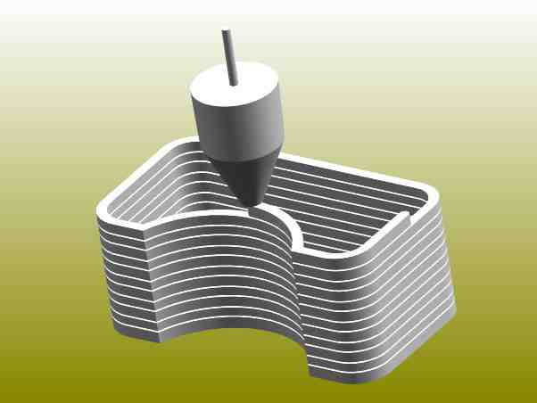
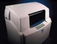
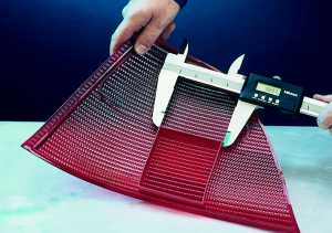
2. Thermojet SOP – (Solid Object Printer): 3D Systems
| Advantages: | Adequate build speed, good resolution, direct investment and RTV castng. |
| Disadvantages: | Support removal, smallest build size (by 6%) of four (4) machine comparison. |
| Worst case scenario: |
Only used for making concept models and student projects. In this case It would be slower and more expensive than the Z-402. |
| Best case scenario: | Fulfills concept model demand with added scope for higher tolerance parts for fit testing via RTV moulds. Lowest capital cost leaves adequate start-up funds available, and a head-start on funding higher RP activities (RTV moulds, urethane castings) |
 |
General comment: Office environment (desktop manufacturing) user friendly, good all-round capabilities. Requires labour for the removal of supports. Company is the leader in RP systems including SLA machines. Build volume 600 in3. Parts have good resolution and are suitable for investment casting but suffer from brittleness and undersurface roughness. |
3. FDM 3000 – (Fused Deposition Modelling): Stratasys
| Advantages: | Thermoplastic material properties, moderate material cost. |
| Disadvantages: | Slow build speed, high initial and system expansion capital outlay and other costs. Eg. Maintenance. |
| Worst case scenario: |
Only used for making concept models and student projects – inappropriate machine for this kind of activity. Commercial models will be well received but higher prices would need to be charged for FDM models due to slow build times, higher material cost and higher capital outlay. |
| Best case scenario: | Strong demand for simulated plastic components for form, fit & functional testing. FDM & SLA are commonly used by RP bureaus for specific applications. |
 |
General Comments: Semi-Office type machine. Popular machine alongside SLA. Parts will be expensive for ordinary concept models – but offer advantage for approximating some realistic plastic mechanical properties. Higher running and maintenance cost. Risk of potential breakdown reflected in high annual service contract ($25k in 2nd year). Replacement heads over $20k. Some surface finish limitations for RTV tooling. Build volume 1000 in3. Material changes require special heads, each $32K. |
4.
LOM-1015 – (Laminated Object Modeller): Helisys ( 2nd hand machine)
| Advantages: | Good dimensional stability, moderate material cost, largest build size. |
| Disadvantages: | Postworking (de-cubing process), laser and air extraction required. |
| Worst case scenario: |
If used only for making concept models and student projects – inappropriate machine. Labour intensive process. |
| Best case scenario: | Low price helps fund further developments. Good for larger parts and directly replaces model-making. |
 |
General Comment: Industrial type machine. Proven technology for casting patterns, models and some direct tooling. Good scope for appearance models since easily finished (like timber). Some skill needed to balance process variables (laser power, lamination intensity) vs (resolution, de-lamination of model). Build volume 2110 in3 |
Comparing Accuracy.
Manufacturer’s
specifications relating to model accuracy and resolution need some
qualification. The repeatability and mechanical resolution of the servo-drive
systems are all very good - far higher than the model itself. Accuracy is mostly
lost at the material-processing interface. Compared against the benchmark
SLA250, the accuracy problems of the systems are listed below. This comparison
is for models without special finishing or polishing.
Accuracy of viable systems (relative to SLA 250 data)
|
% |
System |
Loss
Of Detail due to: |
Bulk Dimensional Changes due to; |
| (100) |
SLA250 |
Laser spot diam., support removal, vertical step resolution | Shrinkage (low) |
| 70 | FDM3000 | ‘Road’ diam., support removal | Thermal shrinkage (low) |
| 65 | THERMOJET | Jet resolution/deposition | Thermal shrinkage (low) |
| 40 | LOM1015 | Laser spot diam., layer thickness | Unisotropic shrinkage - warpage |
| 10 | Z-402 |
Binder bleeding in powder |
Shrinkage, swelling on impregnation |
Comparing Build Speed.
Stated
specifications on model build speed are also in need of qualification. There are
two major classes of system building – planar scan and vector path. The planar
scan method is akin to an inkjet printer, the vector type is more like a
plotter. On average, the scan building is faster, but certain models would be
quicker on a vector path build – especially deep thin walled objects.
The
Z-402 is acknowledged as the fastest modeler. In approximate order of build
speed, the other common RP systems might compare typically like this (Z-402 =
100%)
Z-402
(100%), LOM 1015 (50%), Thermojet (40%), SLA250 (30%), FDM3000 (20%)
These
are very approximate since no standardized benchmarking tests seem to have been
devised for RP build speed.
Summary of Features Analysis

Refer
to Report Appendix 1 for full listing of features analysis data.
DISCUSSION
OF SYSTEMS COMPARISON
Thermojet: Favoured on
basis best value-for-money.
Despite
the fact that the Thermojet offers the smallest build size (by 6%) the models
are sensitive to rough handling and cannot be
painted.
The
Thermojet Multi-Jet-Modeller by 3D Systems appears to be the best
value-for-money RP modeller. On
this alone, the Thermojet has to be the favoured choice. In combination with
silicone tooling however, the Thermojet can produce cost-effective parts
suitable for a wide range of realistic materials and colour choices. We consider
the Thermojet coupled with rapid tooling technology to be the most cost
effective RP + T start-up option.
The
above summary table shows the Thermojet a very close second on overall
performance by the more expensive FDM machine. However, on a value-for-money
basis, the Thermojet is the frontrunner.
These
figures are of an approximate nature and should be taken as a guide only. The
final factor of 24 for the Thermojet is significant however and shows it
received 125% of the ‘votes’ of its
nearest competitor (per dollar).
Z-402: Eliminated on
basis of model quality
The
Z-402 shows the lowest score 16 in the model quality assessment. It suffers
significantly in the area of poor surface resolution, porosity and roughness.
This means that the major parallel technology planned for the RP facility –
silicone tooling – becomes uneconomic. The moulds
could not be cast directly from a Z-402 model unless the model was treated.
This involves impregnation with wax or resin, which covers surface features,
requiring re-work to obtain adequate detail and, with high probability,
resulting in dimensional incorrectness. The Z-402 would be suitable only for
relatively feature-less models like the sole of a shoe or a handle grip. It is inadequate
for simulating injection-moulded parts.
LOM 1015: Eliminated on basis of system complexity, build time and secondary costs
The
LOM machine is excluded because it came second last in every group, and last in
overall score. The LOM 1015 is a second-hand machine, but this veils its true
identity somewhat. New LOM machines
cost over $k200. They use a laser, need installed ventilation and need to be
cooled e.g. water-cooling. The laser is not covered by warranty. The benefits of
LOM are – build volume, strong materials (but not strong enough for functional
testing, so castings would have to be made, for which they are unsuitable
because of unisotropic shrinkage and ……page).
FDM 3000: Eliminated on
basis of high secondary cost, build time.
The
FDM system gives a good overall performance in model quality and utility, but
loses ground in the operational arena – mainly by being expensive. The $25000
annual maintenance fee is prohibitively expensive, and could be an indication of
a system requiring considerable maintenance. Upgrade heads (for different
materials) are $31,250 and there are four of them (one for each material). The
build time is the slowest. A plus is that the parts are, in a limited way,
suitable for functional testing direct from the machine. However, even stronger, more flexible parts with a (much) wider
range of realistic properties
and colours can be achieved by silicone tooling.
|
|
X
Left/Right |
Y
In/Out |
Z Up/Down |
 |
|
Max Print Size |
250 |
190 | 200 | |
|
Resolution (DPI) |
400 |
300 | 600 | |
|
Resolution (mm) |
0.064 |
0.085 | 0.042 | |
|
Resolution (um) |
64 | 85 | 42 |
There are 2 materials supplied by 3D Systems - TJ88 and TJ2000. TJ88 is harder but more brittle. Both materials come in 3 colours - neutral (cream), grey or black. UWS uses the TJ88 Thermojet material. Known as a wax co-polymer, it is essentially a modified wax with a melting point around 70oC. High cleanliness is required to ensure the fine jets are not blocked. One substantial disadvantage of the Thermojet is the high cost of wax - around AUD$4200 per carton (8.8kg).
|
Wax Cost |
$477/kg | 48c/gm | 50c/ml |
As the part builds in height (Z direction), the Thermojet is printing 600 layers per inch (24 layers per mm). Each layer requires several passes because the head works in multiple scans to increase the Y resolution. (Representing the distance between holes). The build speed is increased if the job is short along the X axis, making the passes quicker.
|
Build Speed (mm/hr) |
8mm/hr(full) | 15mm/hr(small) |
|
Build Speed (hrs/cm) |
1.25hrs/cm(full) | 40mins/cm(small) |
Do NOT send native Proe files.
Parts will be checked by Tim Lovett prior to loading to the Thermojet. Cut-off dates for file submission will be announced.
The entire project must be represented in CAD files at the time of submission for RP.
It is possible to use the RP model in combination with hand machined/CNC parts to form a master for silicone tooling.
Submission of parts for RP printing
CAD file of all parts (max 3 RP parts per group design). Preferred CAD format is SolidEdge part file. (This can be exported from Proe and imported to SolidEdge via Parasolid, Step, Iges or other transfer format.
Annotated SE drawing, jpg or other 2D graphics image/drawing showing: The orientation for TJ printing, the volume of the part in ml (cubic cm), the height of the part when orientated as a TJ print, the area (sq cm) of the footprint of the part, overall length & width of the part.
Output from TJ Quoter for all parts allocated for RP.
| Asking Questions | Email questions to Tim Lovett at uwsthermo@yahoo.com.au |
| Sending CAD data |
You can also send CAD files to uwsthermo@yahoo.com.au. Best to zip files. (winzip) Email file limit is 6Mb, so project submissions should be on disc only. Use email for questions or updates of a single part at a time. Preferred CAD format: SolidEdge part files (*.prt )Export CAD format: Parasolid, Step, Iges (If you can't use SE yet) |
| Checking latest information |
For project updates check uwsthermo@yahoo.com.au email address, using the password thermojet. |
| Pricing your RP parts |
To price your RP parts use checkit.exe, which will be available at the uwsthermo@yahoo.com.au email address, using the password thermojet. This program requires CAD information such as part volume (ml or cc - cubic cm), max dimensions of part (x,y,z as presented for TJ printing), and part footprint area (sq cm). It also checks wall thickness in proportion to the size of the part. |
Ask Tim Lovett at uwsthermo@yahoo.com.au
Project timeline:
| WK | Day | LECTURE | TUTORIAL | PROJECT MILESTONE |
| 1 | M 20 Aug | |||
| 2 | M 27 Aug | |||
| 3 | M 03 Sep | TL Remote | Website Up | |
| 4 | W 12 Sep | TL 9am! | TL Remote | Useabilty studies |
| 5 | W 19 Sep | TL 9am! | TL Remote | Model fab: Barnes demo Wed 10am |
| Brk | M 24 Sep | TL Remote | Model fab (Break) | |
| 7 | M 01 Oct | TL Remote | Model fab | |
| 8 | M 08 Oct | TL Remote | Submission of CAD files - Rp feasibility & costing | |
| 9 | M 15 Oct | TL Remote | Presentation Assessment | |
| 10 | M 22 Oct | TL Remote | Submission of CAD files complete review | |
| 11 | Th 01 Nov | TL Wed/Th | RP Silicone Tooling | |
| 12 | Th 08 Nov | TL Wed/Th | Silicone Tooling / PU Casting | |
| 13 | Th 15 Nov | TL Wed/Th | Silicone Tooling / PU Casting | |
| 14 | M 19 Nov | Study Week | ||
| 15 | M 26 Nov | Exam week | ||
| 16 | Th 06 Dec | ASSESSMENT |
The following pictures are from the MCP (HEK) website: http://www.mcp-group.de/english/b_vakuumle.htm. MCP is a manufacturer of Vacuum Casting equipmen
t which is used to mix and inject the resins into the silicone mould under computer control in a vacuum. This is the best way to ensure bubble-free parts. However, good results usually can be achieved by careful use of gates and vents, and by pushing excess resin out the parting line, where bubbles often accumulate. A limited number of smaller complex parts may need to be vacuum cast off-site if adequate void elimination cannot be achieved by conventional methods. Note that all pressure must be released immediately once the mould is filled, otherwise the mould will remain distorted during PU cure.
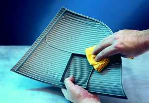
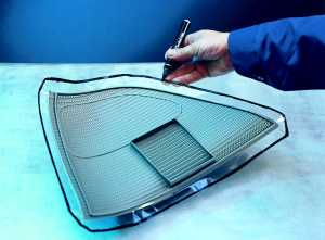
| STEP
1 Thoroughly clean the master model and if necessary apply mould release agent. TJ wax masters can be painted with mild solvent based paints such as enamels. Aggressive solvents can cause the surface of the wax to craze. (Lacquer thinners is difficult to use) Smoothing of the wax can be achieved with
White Spirits (dry cleaning fluid), or careful use of medium solvents
such as enamel solvent. Use a lint free cloth to wipe the surface. Nylon
stocking works well for smoothing out under surface roughness.
|
|
|
|
STEP
2
Establish
the model's eventual parting line using clear adhesive tape and colour
the edge with a marker pen to later
assist in removing
the master model from the silicone tool. Use 3m Magitape, the adhesive
on this tape does not interfere with curing of the silicone. (Ordinary
sticky tape will inhibit the cure of silicone on the sticky side of the
tape) |
|
|
|
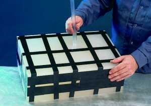
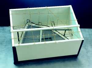
STEP
3
A casting frame is constructed from ABS or laminated chipboard. Tape it up to prevent leaks! Casting gates are attached to the model (or they could be included as part of the wax design) and the model is suspended in the casting frame. Venting rods are attached to provide inlet for resin (gate) and outlet for air (vent/s). Try to gate to the bottom and let the part fill up to the parting line where venting can occur. Air pockets on the top of bosses etc will need their own venting hole (small).
|
|
|
|
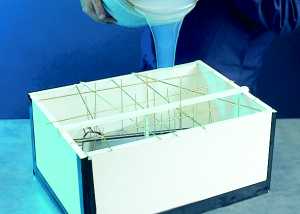
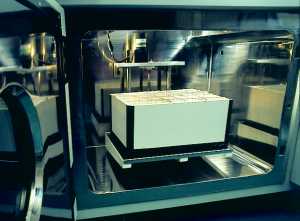
STEP
4
De-gassed
Silicone Rubber is then poured into
the casting frame. Prior de-gassing helps to reduce the amount of
expansion during de-gassing of the mould. After mixing, the silicone
will expand approx 4 to 5 times original volume as air bubbles expand
and collapse. You do not need to completely remove bubbles while under
vacuum because small bubbles dissolve back into the silicone as it
settles. |
|
|
|
STEP
5
After further de-gassing in the vacuum chamber the tool is removed to the oven to cure. The cure rate of silicones is very temperature sensitive. Since the TJ wax is safe to about 40C, Wacker 4644 Silicone will take approx 5 hours to cure. Excessive curing temperatures may create an oversize mould too! A post-cure is recommended for moulds that need to last for many castings - after setting the wax is removed and the silicone heated to higher temperatures (See data sheets).
|
|
|
|
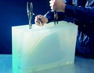
STEP
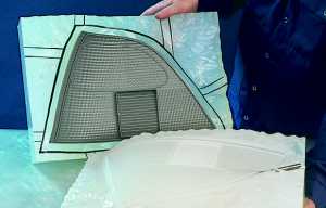
6
When
fully cured and removed from the frame,the
silicone rubber is then cut following the visible parting line marked on
the tape edge. Expanding pliers help to open the silicone while it is
being cut. The cut is made deliberately uneven to aid the locating of
the 2 halves of the mould. Care needs to be taken to avoid undercuts of
silicone or fingers. |
 |
|
|
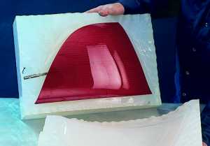
STEP
7
The
master model faithfully reproduced in the silicone. The master model is
then removed. Notice the roughness of the opening cut. Notice the tricky
sticky tape leading out from the parting line tape - this helps to make
the opening cut easier and also works as a venting system around the
parting line. Very clever. Use
a mould release agent on the casting surface to enhance the life of the
mould.
|
 |
|
|
STEP 8 The tool is taped together and prepared for casting. Don't tape it too tight because the PU will be heat cured - and silicone expands significantly with temperature. A tight taping will produce an undersize part. Use
a tape with similar expansion properties to the silicone, such as
flexible PVC tape (electrician's tape). Notice the huge gate tube - the
MCP systems uses no pressure so a larger gate is used. You should be
able to keep this down if you inject instead. |
|
|
|
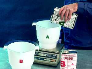
STEP 9 Vacuum Casting Resins A+B are precisely measured
by weight.
|
 |
|
STEP 10 Thoroughly mix the resin - then add
colour or fillers. Some resins don't like colour added first (eg
polyester) because it can hinder the chemical mixing of A&B parts. Quickly de-gas the mixture and load into injector
attached to the mould. Inject the mixture into the silicone mould,
allowing a little overfilling to help expel bubbles. Release any
pressure to allow mould to return to correct shape. |
|
|
STEP 11 The whole tool is loaded into oven for curing, then the the cast resin prototype is removed from the tool. It comes away easily from 4644 silicone, air gun can aid removal also.
|
|
|
STEP 12 The cast component is an exact
reproduction of the master model. Casting gates and runners are trimmed
off - its nice if they're thin here. It is normal to |
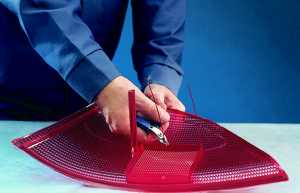 |
| STEP
13 Finally, checked for dimensional accuracy to master model the component is now ready for final finishing (Which probably means minor cleaning up, polishing of painting). Sometimes is is easier to drill holes afterwards, especially when the holes are not in the line of draw of the moulding (so become columnised in the TJ print)
|
 |
|
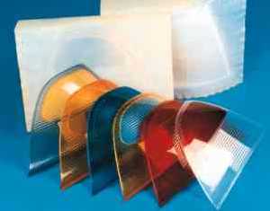
(Advertisement for MCP) MCP offers all users the specialised technology of producing multi- coloured castings.
(I thought I should do that seeing as I
stole their pictures) |
 |